————————————————————————————————————————————————————
How to : Fit flashing indicators to a early (semaphore) bus .
————————————————————————————————————————————————————
Early buses didn't have indicators on, they only had semaphores. This meant that people driving
near had a restricted view for these turn signals, particularly the cars behind the vehicle. Pulling out
onto the motorway or into side roads can be quite scary.
So as a matter of safety and peace of mind, you may decide to fit some type of flashing indicator.
This is one answer to the problem of solving how to fit flashing indicators.
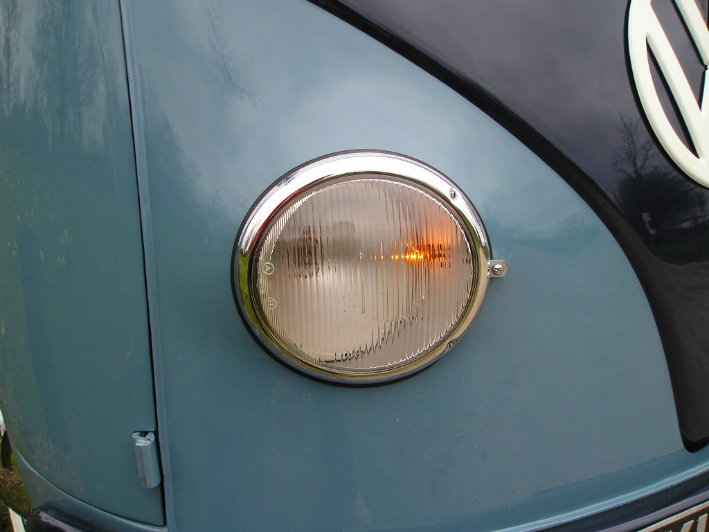
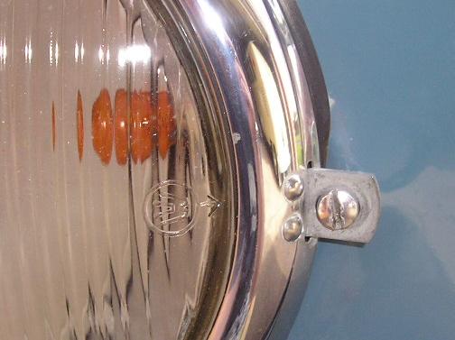
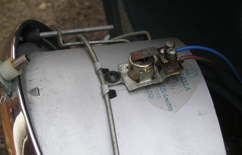
The front indicators are housed within the headlight on the retainer (similar to some beetles).
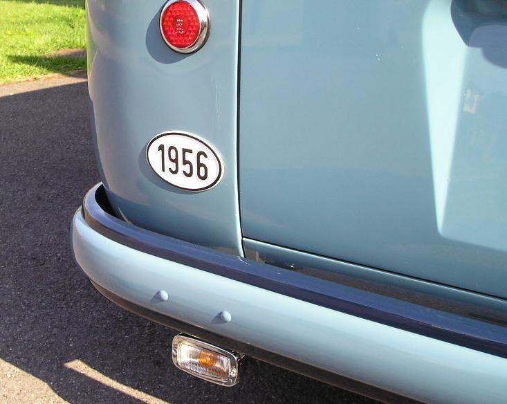
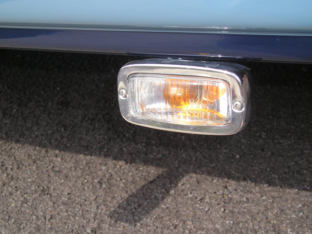
The rears are external period style reversing lights mounted on homemade brackets
Both indicators bulbs are amber glass single filament.
What parts you need : 2 Beetle bulb holders (from beetle headlight retainers).
2 Hella Style Reversing Lights.
4 Orange Bulbs (12v or 6v)
2 Relays (12v or 6v)
2 Brackets ( for hanging Hella lights)
Loads of wire (coloured to your choice)
What tools you need : Various sized drill bits
Soldering Iron & Solder
Cable Ties & Cable Ties Holders (self-adhesive or screw type)
Wire Strippers, Screwdrivers (flat & cross head)
Brief Notes:
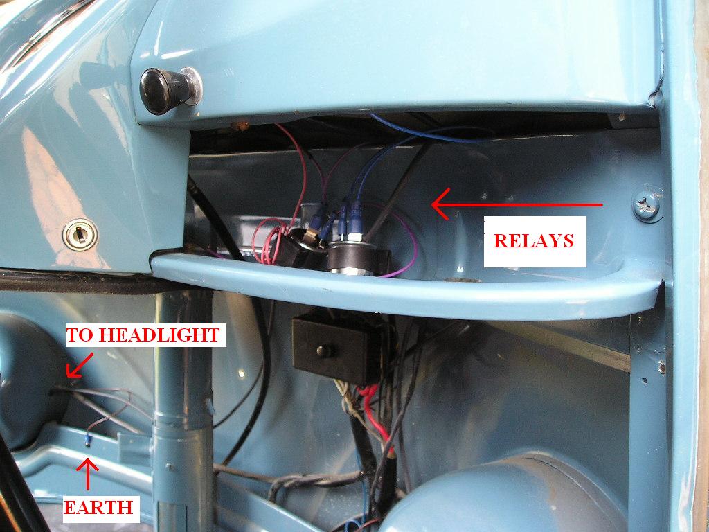
The relays (one of each side) are mounted under the dash, with different colour wire for each side.
The front earths are just inside/behind the kick panels and the rears are onto the bumper bracket.
The front bulb holders are self tapped into the original headlight retainer and a large hole is bored
so that the bulb itself can be placed through the retainer too.
I routed the rear indicator wires through the cab section, along the floor panels then around the
rear chassis rail to the bumper bracket. (see pics 5.6.7.)
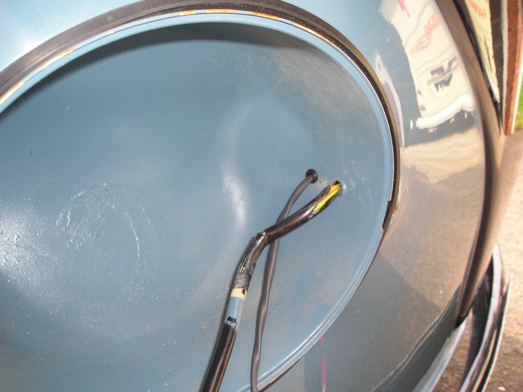
1. The front indicator wire passing thro the headlight bowl with grommet.
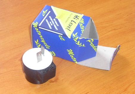
2. A two pin relay and its box.
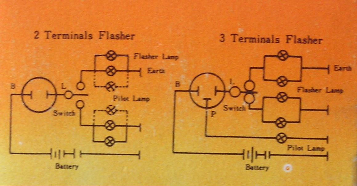
3. Relay diagram for two pin and three pin.
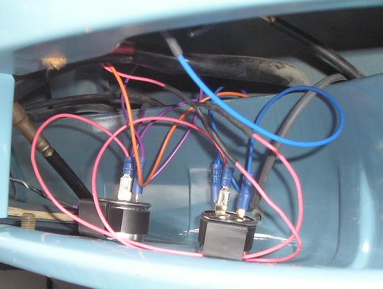
4. Relays in place under dash, coloured wire for each side. (waiting to be cable tied up).
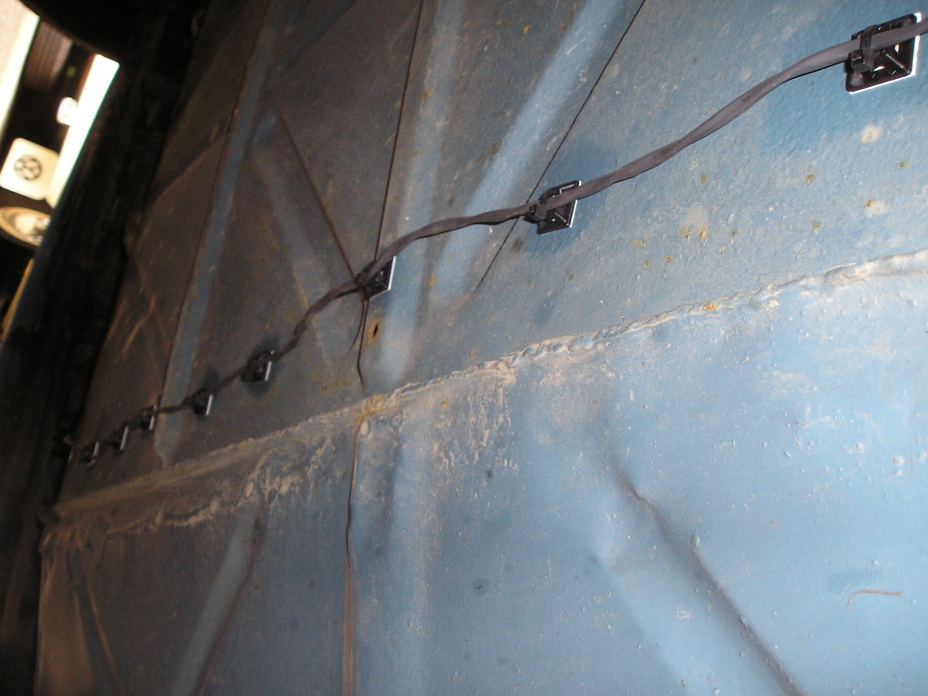
5. The rear indicator cable cable tied underneath the van.
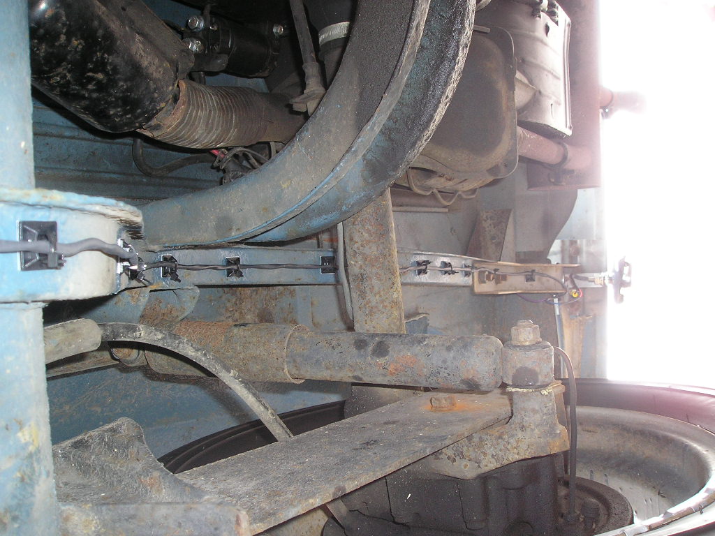
6. The cable route is shown around the rear bodywork.
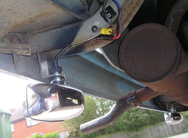
7. The earth and cable end with bracket and light.
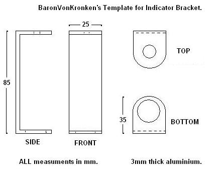
8. Rear Indicator Bracket Template.
Note: To view photos in greater detail, right click mouse on photo, then (save picture as).
![]()